

News centres
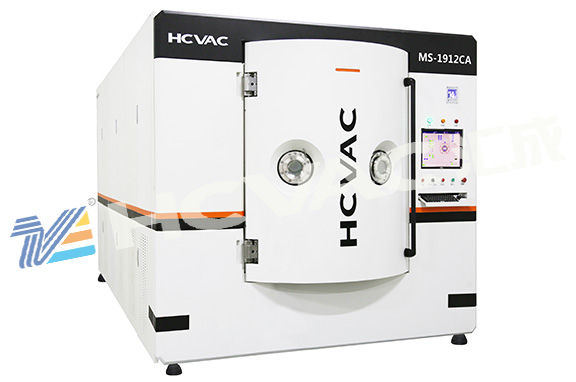
The electrical control system of the vacuum coating machine is divided into three main parts: control cabinet, transformer group and operation table. The control components of all functions of the equipment, including programmable PLC, frequency converter, voltage regulating module, etc., are installed in the control cabinet. The front of the control cabinet is equipped with resistance and ionization compound vacuum gauges, and the heating current meters of booster pump and diffusion pump are installed. And three-phase power supply indicator, alarm indicator, emergency stop switch.

The transformer set is installed under the vacuum tank, and the positive pole of the output terminal is directly connected to the corresponding evaporation electrode rod, and the negative pole of the output terminal is connected to the negative electrode of the evaporation after butting. The operating table is placed in front of the vacuum tank and under the observation window. The touch screen, operation control buttons, knobs or switches of each component are all set on the panel of the operating table. The touch screen is located in the upper left part of the operation panel. The winding system parameters, including the tension of unwinding and unwinding, the winding diameter, the setting and data display of the machine's operating speed, and the operation instructions of the vacuum system are all carried out on the touch screen.
The upper right part of the operation panel is the evaporation source heating power adjustment knob and ammeter, which can adjust and display the power of each group of evaporation sources.
The lower part of the operation panel is a function control button or switch, including control power switch, winding car forward and backward, swing arm forward and backward, bending roll forward and reverse, wire feed switch and speed, cover switch, system operation control mode selection, etc.
The user should set up a separate power switch box for the machine near the vacuum coating machine, prepare a power cord, and connect the power supply to the terminals of the machine code-named R, S, T, and N.